Caustics: Light Concentration by Reflection and Refraction
Caustics are bright curves or patches that appear when many light rays get concentrated into a smaller region. You can think of them as a light-density effect. Where rays spread out, brightness drops. Where rays bunch together, brightness rises, often into sharp-looking lines.
This is why caustics are so visually striking. They are not random decoration. They are geometry made visible by light transport.
If you have seen shimmering patterns on a pool floor, bright arcs inside a coffee cup, or focused sunlight through curved glass, you have seen caustics in daily life. The optics behind those examples can be explained with simple ray tracing and a few geometric rules.
This tutorial builds that model in three stages:
- Reflection caustics from a curved mirror with an adjustable light source.
- Circular reflection caustics (the coffee-cup style curve).
- Refraction caustics from a wavy water surface onto a pool floor.
Core Idea: Ray Density Creates Brightness
A useful mental model is to emit many nearby rays and track where they land. If neighboring rays end up close together, energy per area increases there. That high-density zone is the caustic.
In geometric optics terms, caustics are often described as an envelope of a ray family. You do not need advanced differential geometry to use this idea practically. In simulations, a simple approximation works well: trace many rays and look for where adjacent rays intersect or cluster.
Two mechanisms produce most everyday caustics:
- Reflection: the outgoing direction depends on the local surface normal and follows equal incidence/reflection angles.
- Refraction: direction changes by Snell’s law when crossing media with different refractive indices.
Both mechanisms are local rules, but the resulting brightness pattern is global. Small normal changes across a curved surface can drastically reshape where rays converge.
Interactive Reflection: Curved Mirror and Movable Source
Start with this curved-mirror explorer. Move the source position and mirror curvature, then watch how the reflected bundle forms concentration lines.
How to read this visualization:
- Blue lines are incoming rays from the source to points on the mirror.
- Red lines are reflected rays.
- Purple dots mark approximate intersections of neighboring reflected rays, which estimate the caustic locus.
What to test:
- Keep curvature fixed and slide the source left-right. The caustic shifts and can twist asymmetrically.
- Increase curvature while keeping source centered. Reflected rays bend faster, and concentration becomes tighter.
- Lower the source height. Angular spread changes, often pushing parts of the caustic upward.
A key insight is that the mirror does not need to be perfect to create a visible caustic. Any smooth curvature that causes direction variation across neighboring normals can produce one. What changes is the exact shape and sharpness.
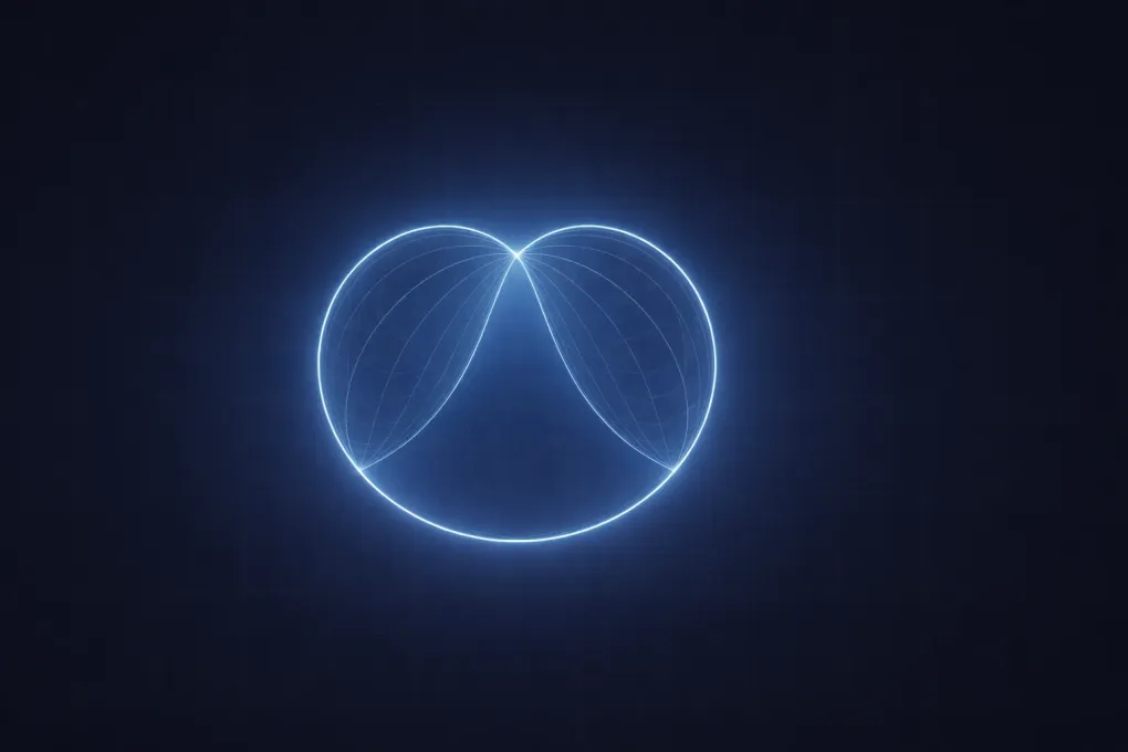
Why Coffee Cups Show Bright Inner Curves
The bright curve inside a coffee cup is a classic reflection caustic. A simple approximation is a reflective circular boundary with oblique incoming light. Each incident ray hits a different wall normal, reflects, and the reflected family develops an envelope.
Use the explorer below to see this process directly.
Suggested experiments:
- Keep the source near the center to see a more symmetric concentration layout.
- Move
Source Xleft or right and watch the bright locus drift and skew. - Change
Source Yto see how source depth inside the cup changes the reflected family.
In the ideal mathematical model of parallel rays reflecting inside a circle, the caustic is related to a nephroid-like curve. Real cups are not perfect circles, liquid surfaces move, and illumination is not perfectly parallel, but the same geometric cause remains: nearby reflected rays concentrate along a structured path.
This is why the pattern looks crisp even though the source can be broad. The cup geometry itself performs directional sorting.
Interactive Refraction: Swimming Pool Caustics
Pool-floor patterns are mostly refraction caustics. Sun rays hit a wavy air-water boundary. Each local wave slope changes the incident angle relative to the normal, so the refracted direction varies from point to point. Those small direction differences become bright and dark bands where rays arrive on the floor. If you want a quick refresher on why ray directions change at the interface, read light refraction, Snell’s law, and refractive index fundamentals.
Use the refraction explorer below.
What to observe:
- Increase wave amplitude: normal variation grows, so bright/dark contrast on the floor increases.
- Increase wave frequency: caustic bands become finer and more closely spaced.
- Change sun angle: the entire pattern shifts laterally and reweights where concentration peaks appear.
- Adjust water index: stronger bending generally increases relocation of hit points and can tighten concentration regions.
The highlighted floor strip represents relative ray-hit density. Brighter yellow sections mean more traced rays landed there, which approximates higher irradiance.
Even this 2D toy model reproduces a core real-world behavior: dynamic surface normals convert smooth incident light into complex moving light textures.
Mathematical Thread Connecting All Three Cases
The details differ, but the computational structure is shared:
- Sample surface points.
- Compute local normal.
- Apply direction update rule.
For reflection at each point with incident unit vector and surface normal :
For refraction from medium 1 to medium 2, the transmitted direction follows Snell’s law at the interface:
Once new directions are known, trace rays to a target plane (or continue with further bounces), then estimate density. That density field is what your eye perceives as caustic brightness.
So the visual drama comes from a simple pipeline: local normals -> direction mapping -> spatial concentration.
Practical Ray-Tracing Notes
If you later build this in a renderer or simulation, these decisions matter:
- Sampling density: sparse rays miss thin caustics; more rays improve stability.
- Surface smoothness: noisy normals create noisy patterns; smooth surfaces give coherent caustics.
- Intensity weighting: physical models include Fresnel terms, absorption, and area Jacobians.
- Temporal coherence: moving surfaces need stable sampling to avoid flicker.
The visualizers here intentionally focus on geometry-first intuition. They ignore some energy terms so the concentration mechanism is easier to inspect. That is usually the right learning order: understand ray routing first, then add full radiometry, just as rendering-focused techniques like ray marching with signed distance fields separate path construction from later shading detail.
Common Misconceptions
A few misconceptions often block understanding:
- Caustics are not only a “glass” phenomenon. Reflection alone can generate them strongly.
- Caustics do not require lasers. Broad sunlight can produce sharp patterns if geometry concentrates rays.
- Bright curves are not drawn by surface texture. They are generated by directional transport.
- Random-looking shimmer in water is often deterministic geometry plus moving waves.
When debugging a scene, ask: are normals directing neighbors together or apart? That question usually predicts where bright lines will appear.
Recap
Caustics are concentrated-light structures caused by reflection or refraction over curved geometry. The same principle explains:
- pool-floor light networks,
- bright curves in coffee cups,
- and focused highlights from glass or mirror surfaces.
If you keep one model in mind, use this: trace many nearby rays and watch density evolve. Where ray families fold and cluster, caustics emerge.
That model is simple, mathematically grounded, and powerful enough to bridge everyday observations with advanced optics workflows.